Build Your Hopper
Every chapter of the build video, written out in the same order, with a picture from the footage at each step. The same steps, in a different medium.
No screw on Hopper gets tightened. Drive it until it stops, and leave it lightly snug. That is true of every screw in this guide.
Install the motors
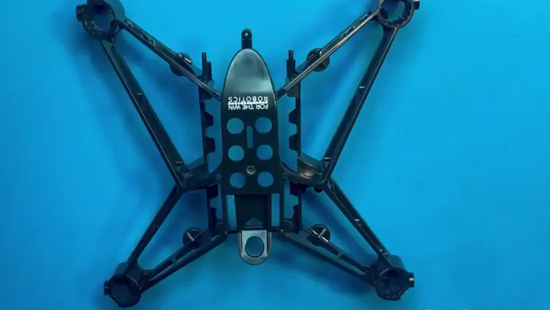
Position the airframe logo forward. That is the front of Hopper, and every placement below is described from there.
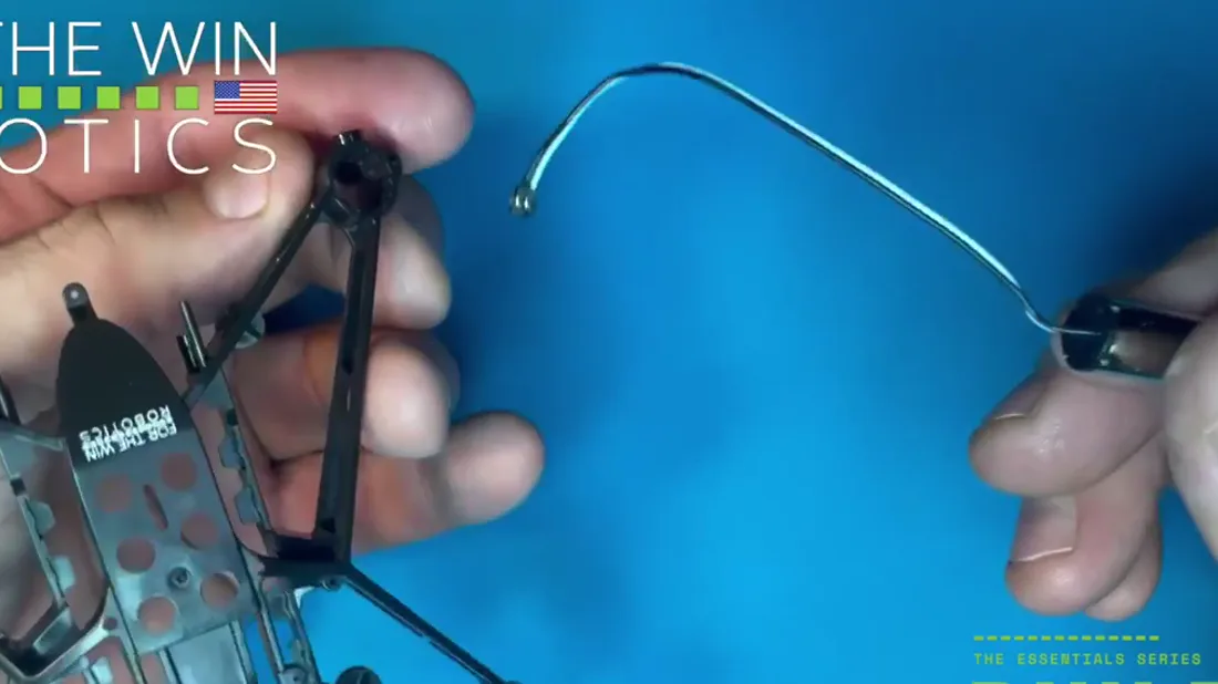
Motor A has the white and black wire. It goes first, in the front right motor mount.
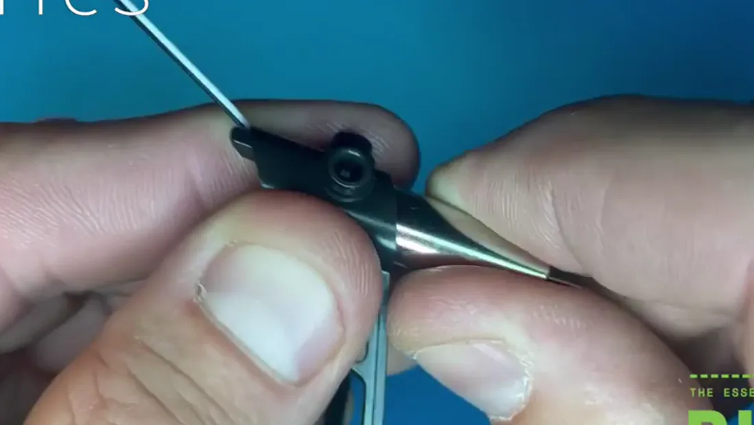
Seat it by hand until the motor sits snugly in the channel, then pick up the motor tool.
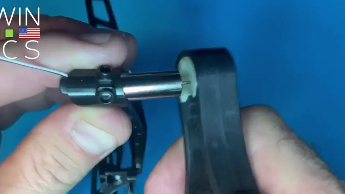
Insert the motor into the tool. Be careful not to bend the motor shaft. A bent shaft is a dead motor.
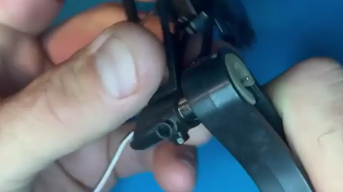
Squeeze the motor in the tool and press it into the channel. It stops on its own against the protrusion inside, leaving the motor sitting about an inch and a half out of the channel.
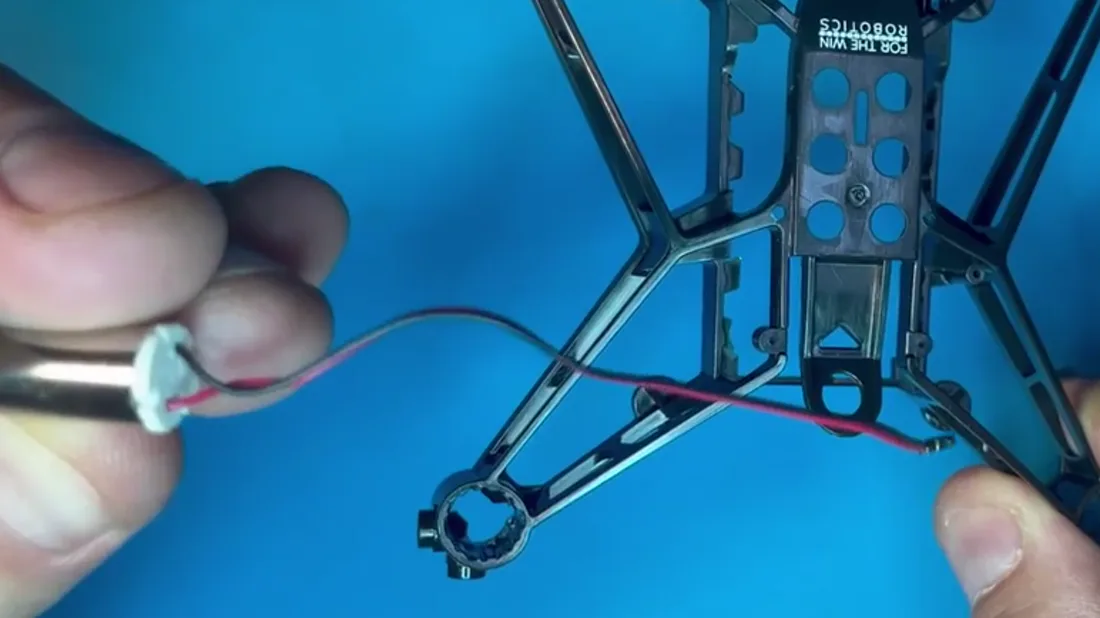
Motor C has the red and black wire. Looking at the front of the drone, it goes in the front left channel. Start it by hand, then press it home with the tool.
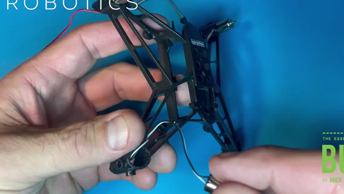
The second motor A goes diagonally across the airframe from the first. Thread the wire through the channel, start it by hand, finish with the tool.
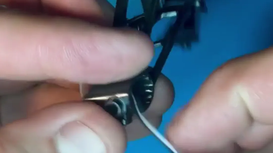
The motors are keyed, and so are the motor channels in the airframe. Each channel is built to accept only its corresponding motor.
The key is a guide, not a lock. The wrong motor can still be jammed into a channel, so if a motor feels unusually hard to seat, stop and check you have the right one for that position rather than forcing it.
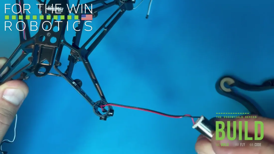
The last one is the second motor C, diagonal from the other C. Red and black wire. Thread, start, press.
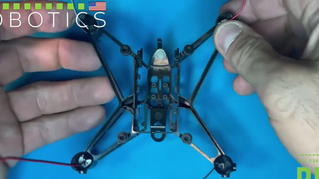
With all four in, press each one down once more to close any gap, then flip the airframe over.
The motor wires are loose at this point. That is fine, and this is a good place to leave them.
Inner front faceplate
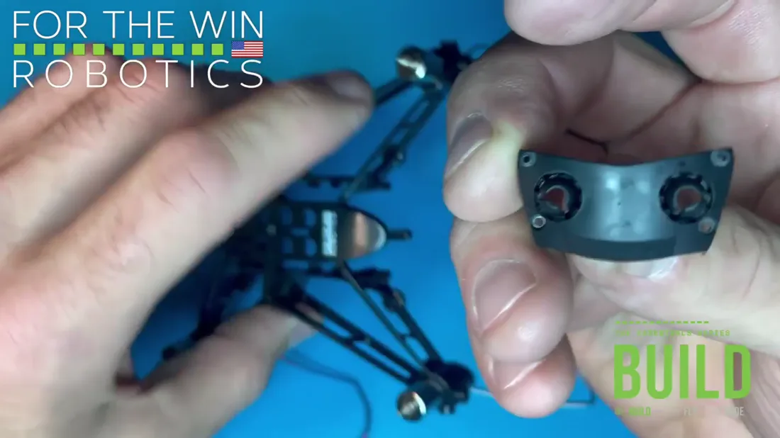
The faceplate has two sets of holes, top and bottom. Only the bottom pair takes screws.
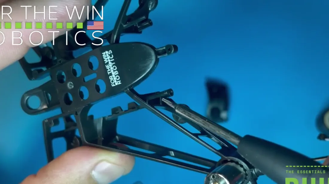
The top pair is a joint, not a fastening. The airframe's two long cylindrical protrusions slide inside the larger receiving cylinders on the faceplate.
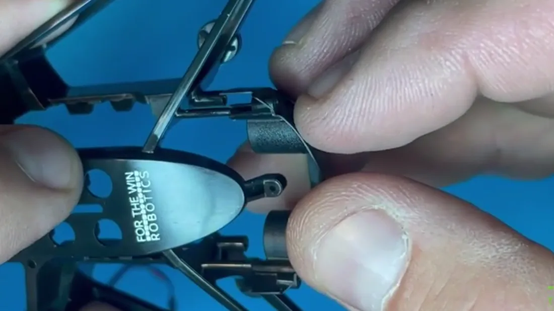
Line the two up and thread them together gently, then press down until they seat.
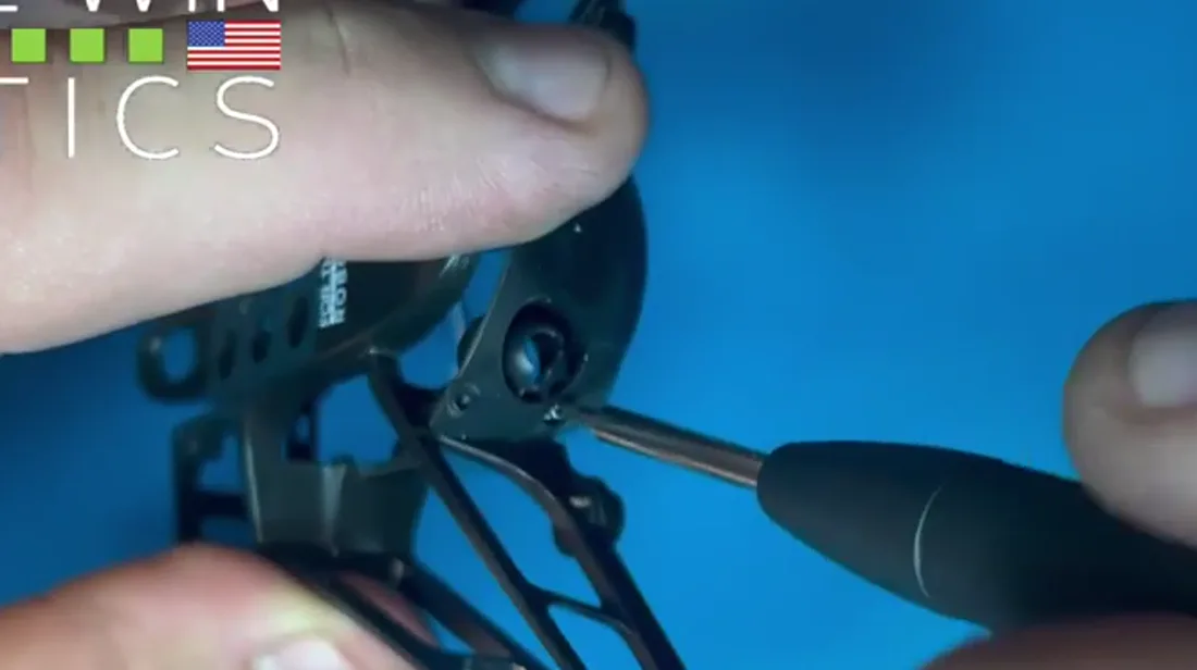
Now the bottom pair. Put a screw through the faceplate hole and into the threaded airframe hole behind it. Turn until you feel tension, then stop.
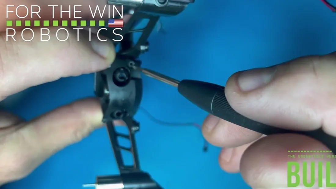
Repeat on the other side. The T3 screwdriver is magnetic, so the screw sits on the tip while you line up the hole.
Printed circuit board
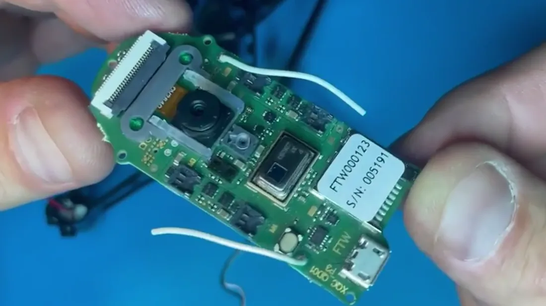
Know both faces before it goes in. Bottom side: the IR sensor, the lens, the motor ports, and the Bluetooth and WiFi antennas.
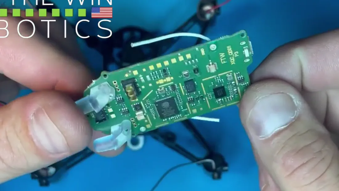
Top side: the light guides, which are Hopper's eyes, the power connector, and the four pin connector for whatever attaches in future.
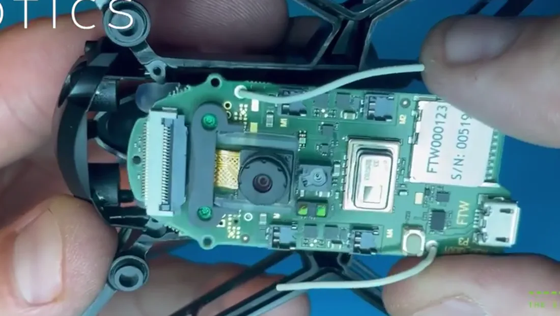
Turn the airframe over and lay the PCB in with the bottom side facing up.
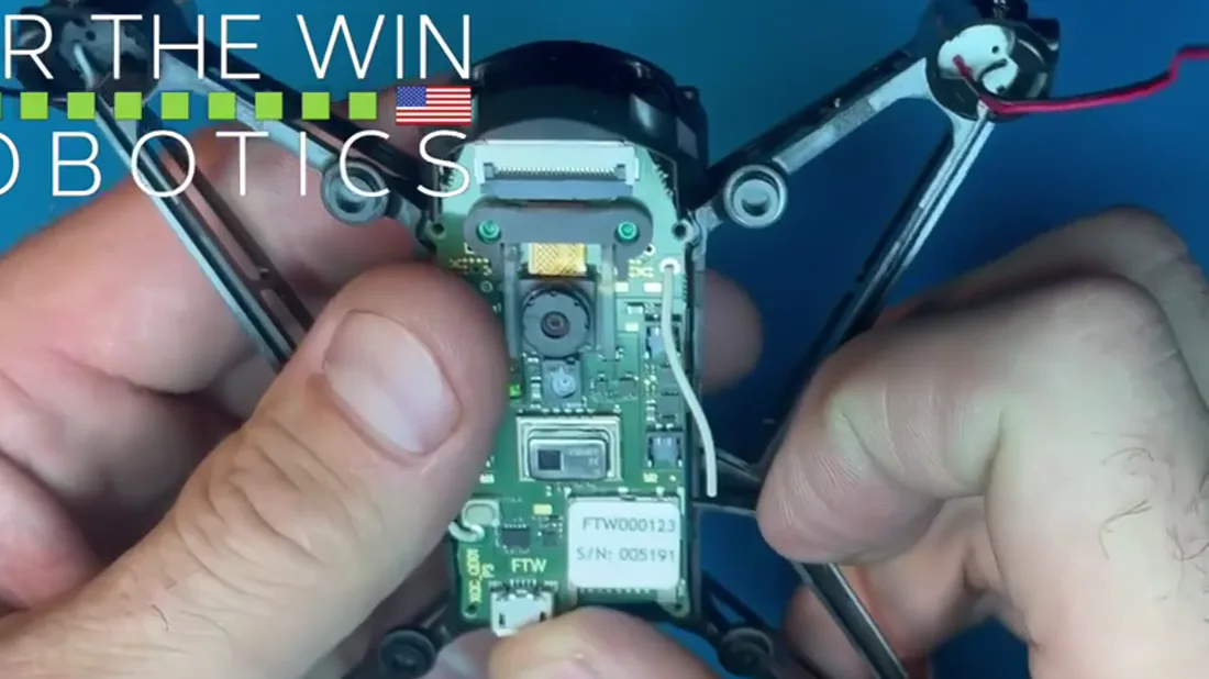
Go gently, so the light guides slide into the eye channels in the interface plate. It clicks into place and the airframe holds it.
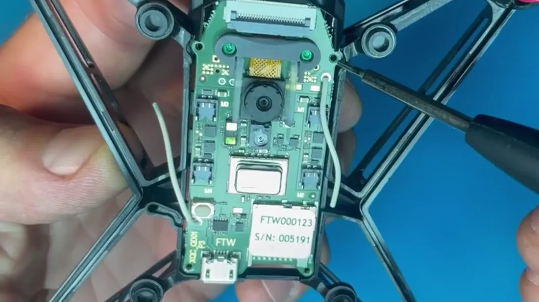
Check that the four screw holes on the top side and the two on the bottom line up. Nothing gets screwed down yet. You are only confirming it sits right.
Antennas
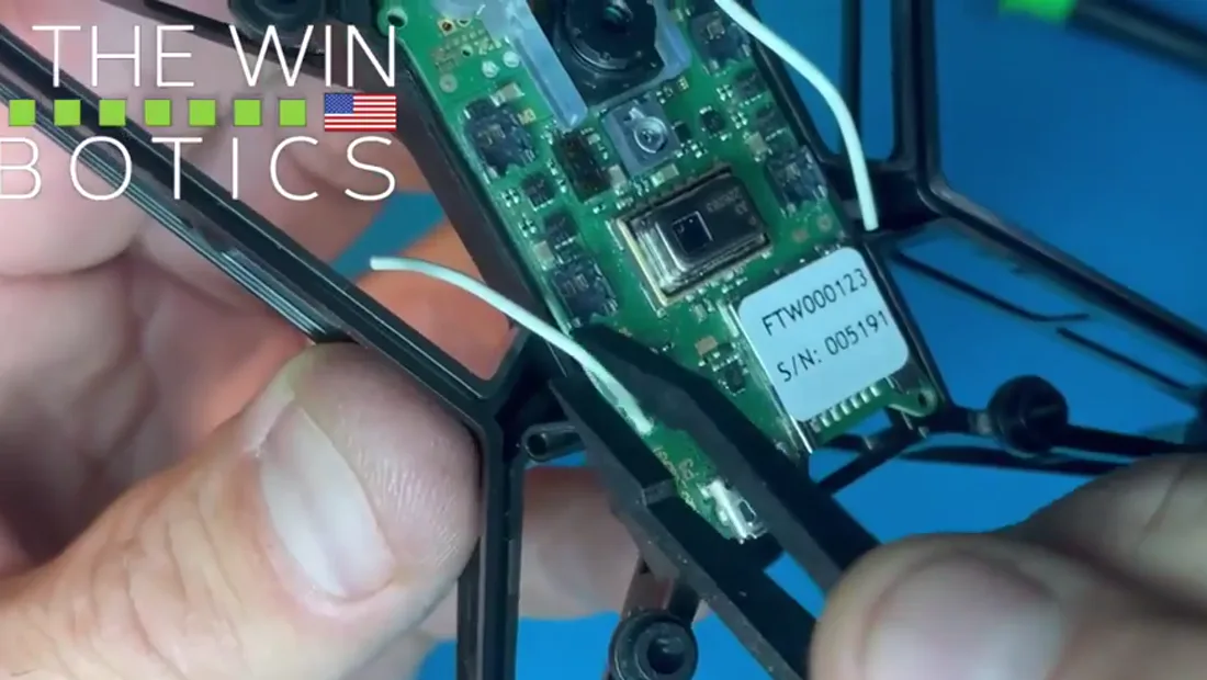
Still working on the underside. The Bluetooth antenna is the one furthest from the lens.
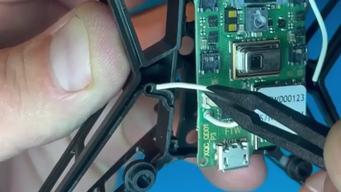
Feed it through the pre-drilled hole so it sits protected. Tweezers make this easier.
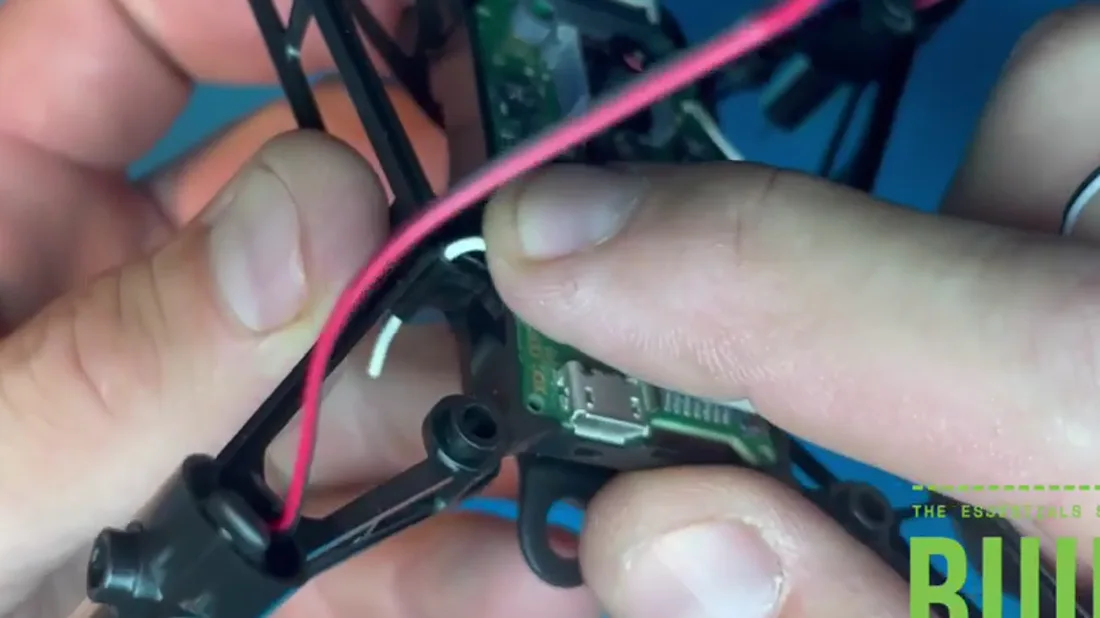
Work it in a little at a time, gently repositioning the PCB as you go so it nests properly into the airframe.
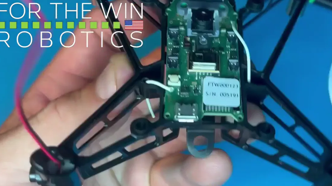
What you are protecting through all of this is the solder joint where the antenna meets the board.
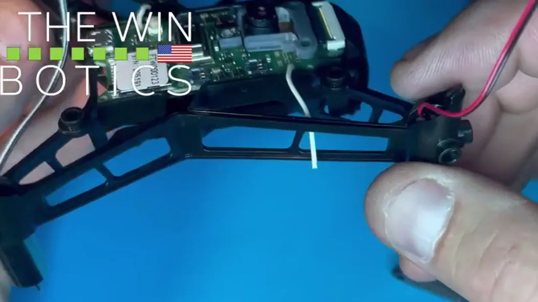
Bend the WiFi antenna gently so it points outward and through the airframe, protected the same way.
If the solder joint does break, it can be re-soldered, and it is not the end of the world. Contact us first.
Motor wire channels
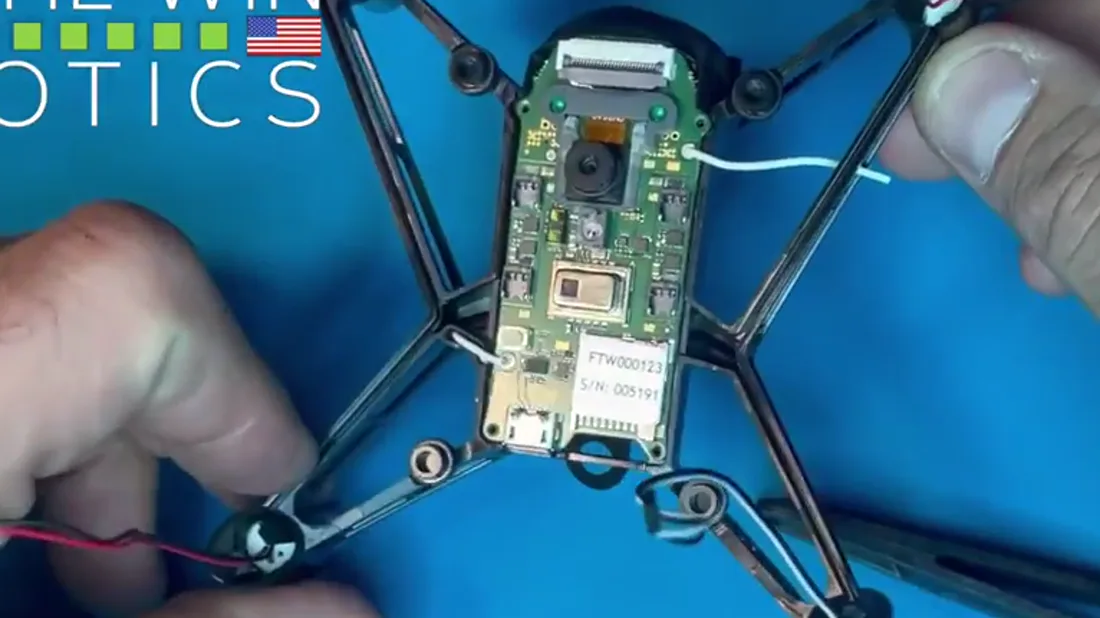
Channels are cut into the airframe to carry each motor wire from its motor channel to the PCB.
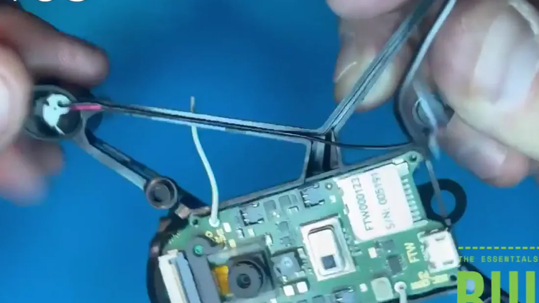
Lay every wire black side up. On a C motor that hides the red, on an A motor it hides the white, and the underside of Hopper comes out clean instead of striped.
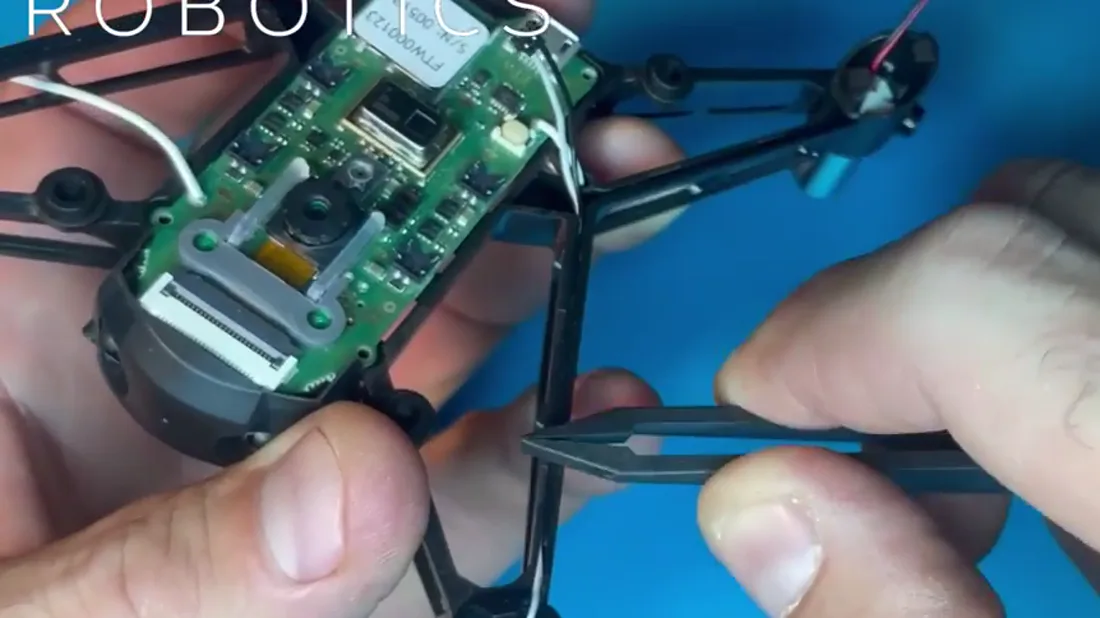
Roll the flat of the tweezers, or the metal of the T3 screwdriver, along the channel to press the wire down smooth and flush.
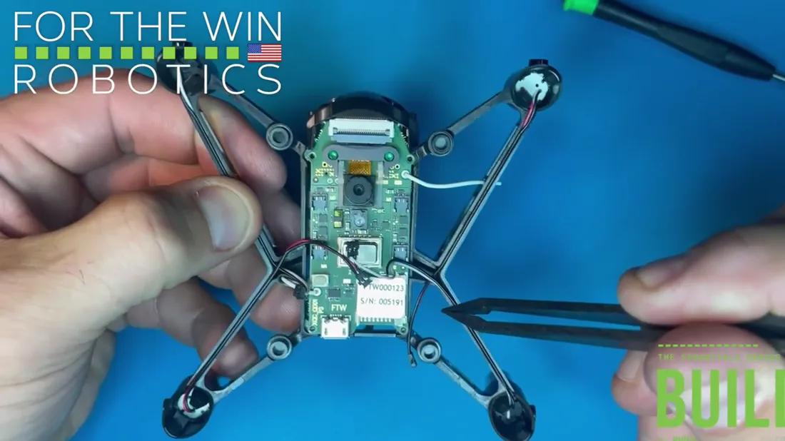
The wires stay put once the feet are on and the connectors are in. If one lifts before then, press it back.
Connect the motor ports
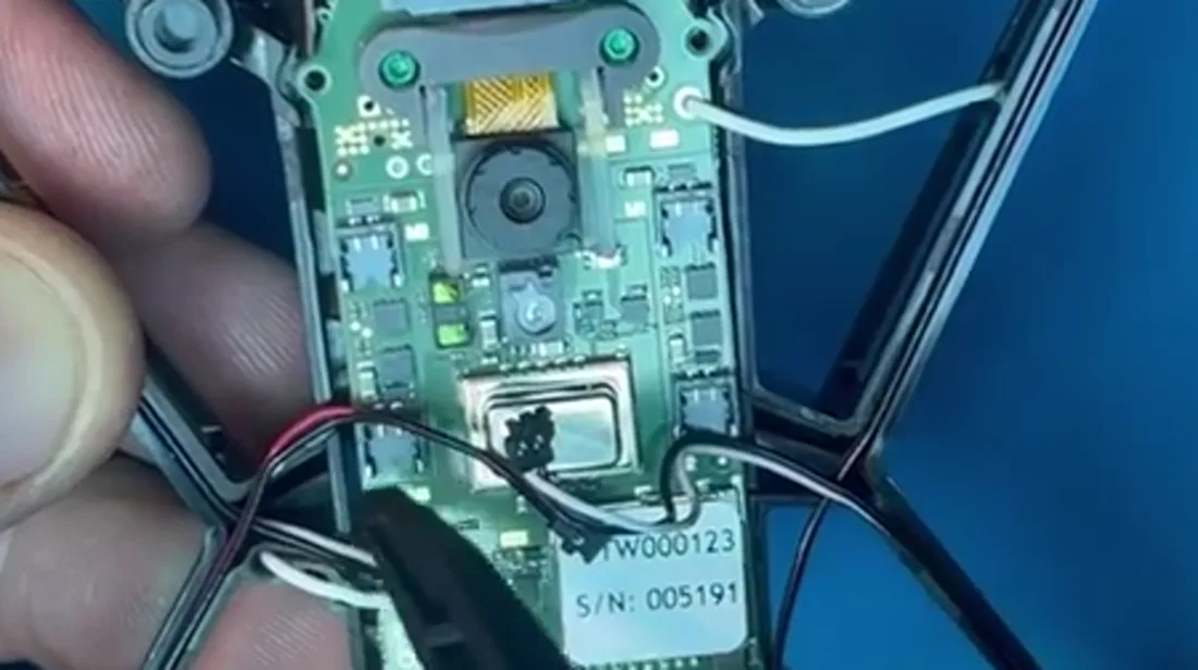
One rule covers all four: each connector goes to the motor port closest to its own motor. It does not matter whether it is an A or a C.
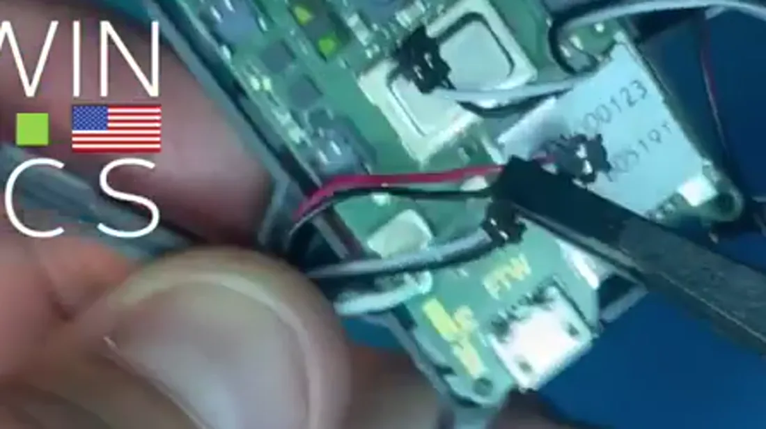
Orient the connector gold circles up.
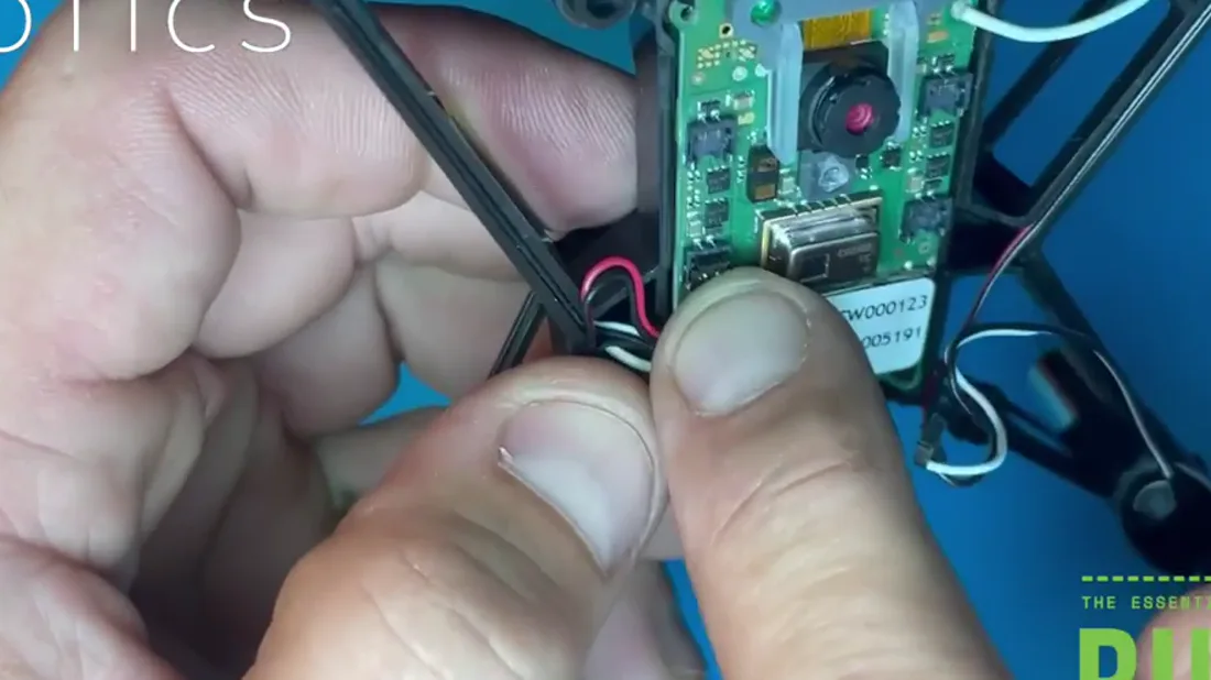
Line it up and press it in with a finger or the tweezers. The click is quiet. What tells you it seated is how it sits afterwards.
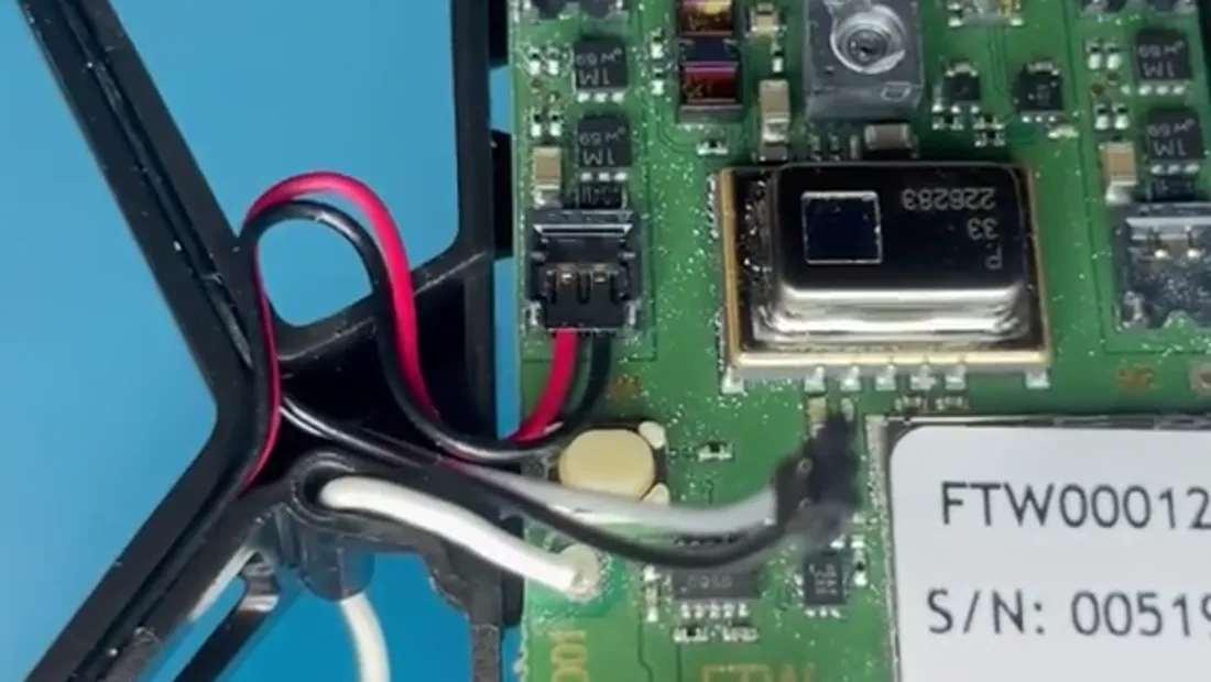
Check it is flat. A connector angled even slightly on either side gives an intermittent connection, and that is a drone that crashes on takeoff.
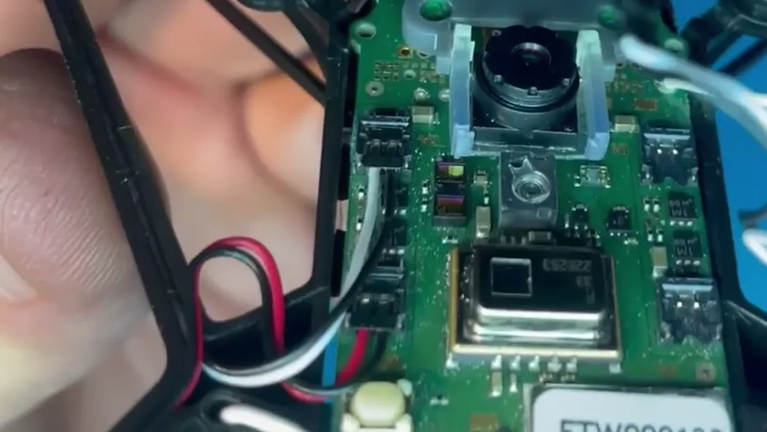
Make sure the wire leaving each connector is clear of its neighbour, and that two ports on the same side are not interfering with each other.
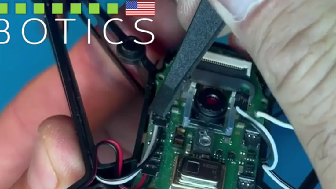
Press down gently and flat with the tweezers to finish the connection.
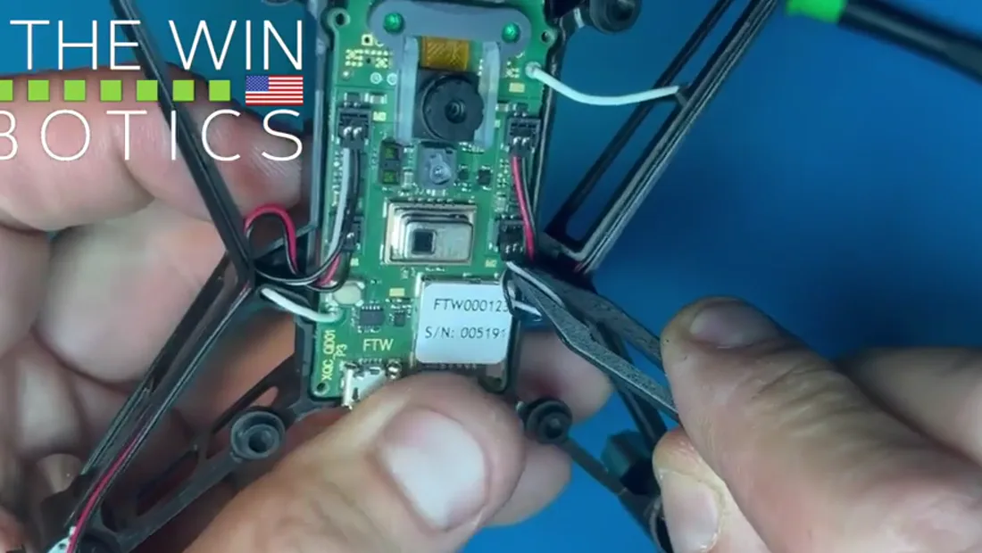
Work around all four the same way.
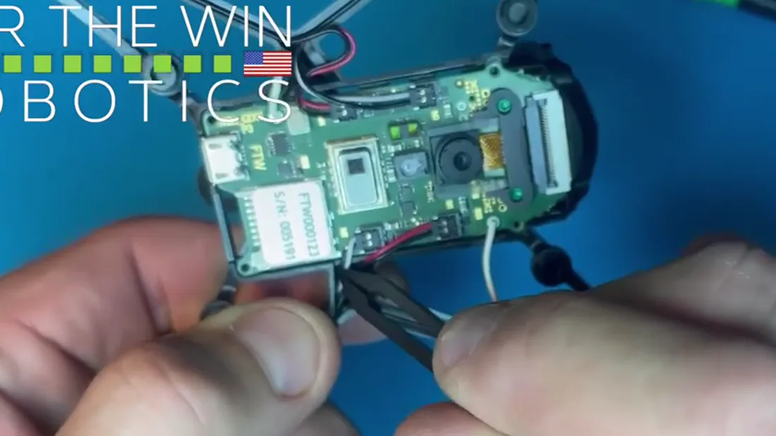
With all four connected, stow the slack. Pinch the excess wire and press it into the channel and the triangular cavity just before the PCB until the channel is full. Go gently, because pressing too hard can pull a wire back out of its connector.
Top body panel
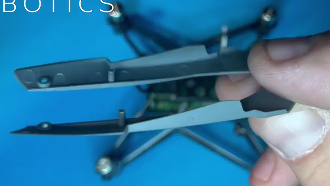
The panel has one protrusion on each side that drops into a hole in the middle of the airframe. The fit is tight by design.
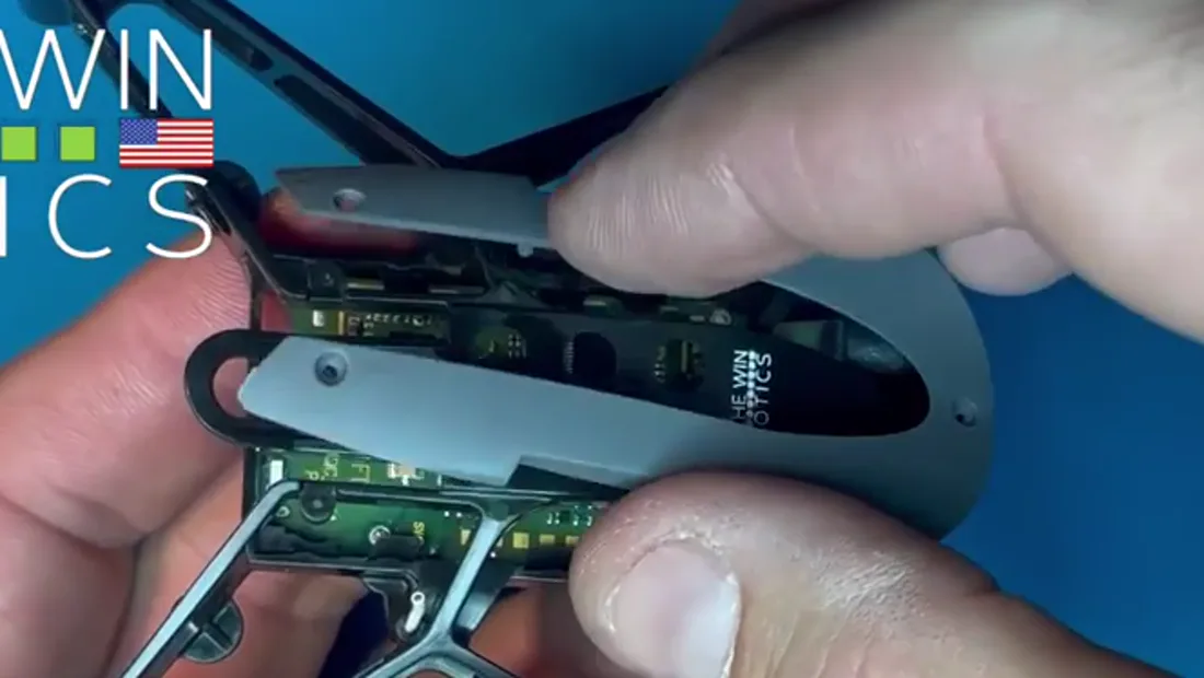
Three screw holes go in later, to mount it more securely. For now it just sits.
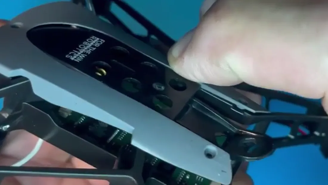
Front and back are visibly different. Line it up the right way round and press down.
Install the feet
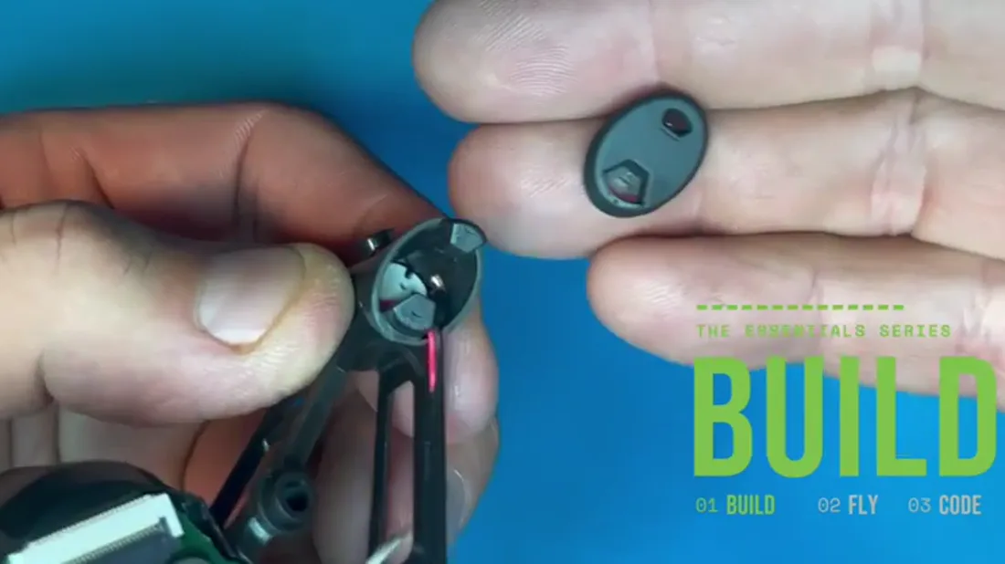
All four feet are identical. Any foot fits any position.
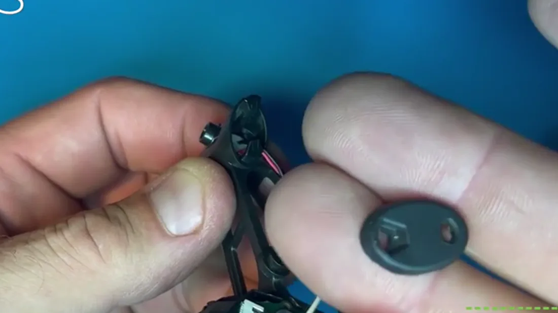
Each foot has a larger hole and a smaller one, and an inside face and an outside face that are clearly different from each other.
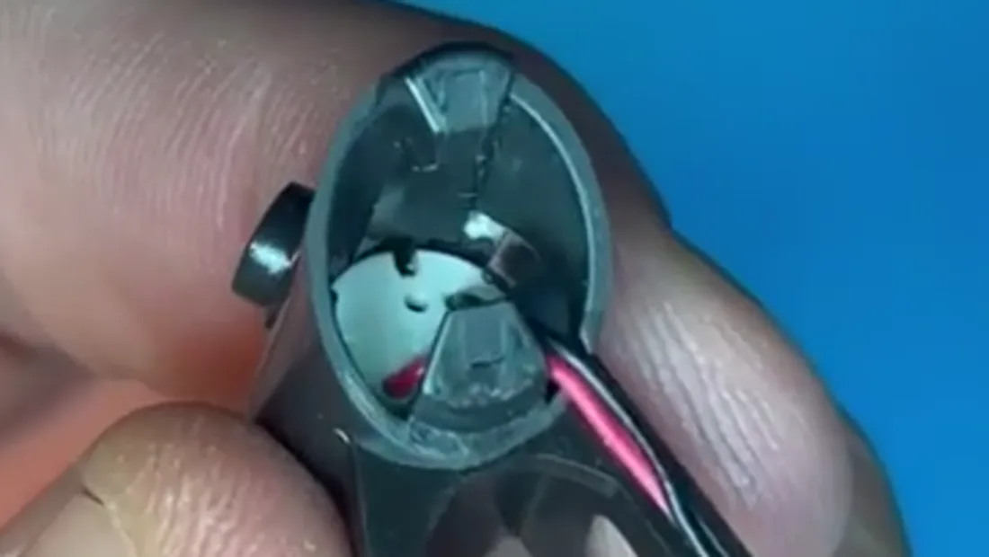
The airframe has two protrusions at each position: the lower one larger, the upper one small.
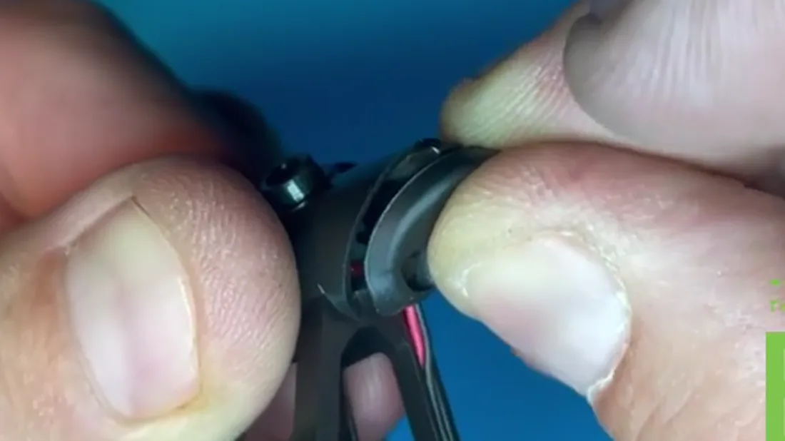
Slide the larger lower protrusion into the foot first, right into the rubber.
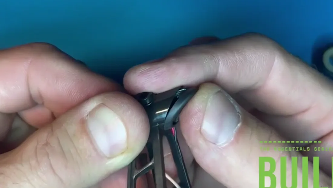
Then pull the foot up and over so the upper protrusion hooks into the smaller hole. The T3 screwdriver gives you the leverage.
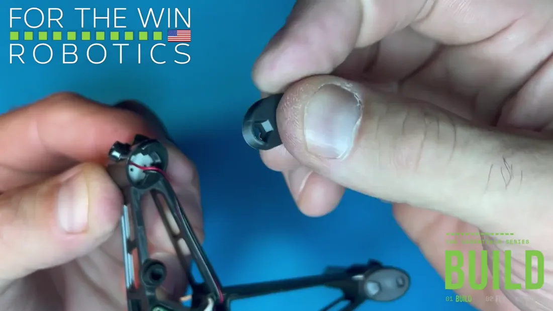
Repeat for the other three, keeping motor wire out of the way as you go.
Face mask
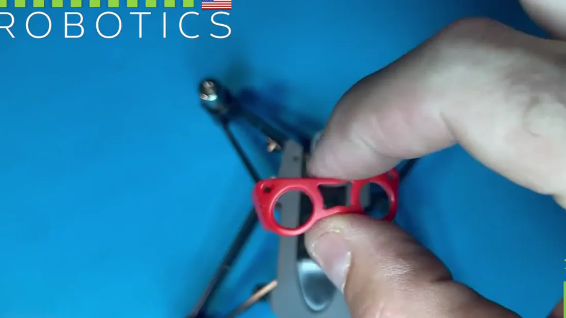
The face mask comes in four colours and every one installs the same way, with two screws.
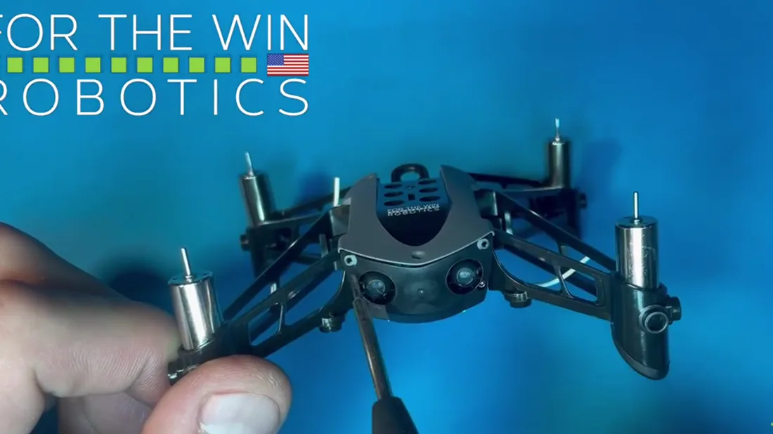
It goes on the top holes of the interface plate, the pair you deliberately left open back at the faceplate step.
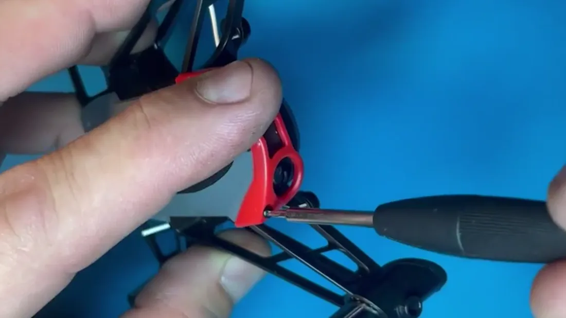
Hold the mask and the drone together, get a good look at the first hole, and confirm it is lined up before the screw goes anywhere.
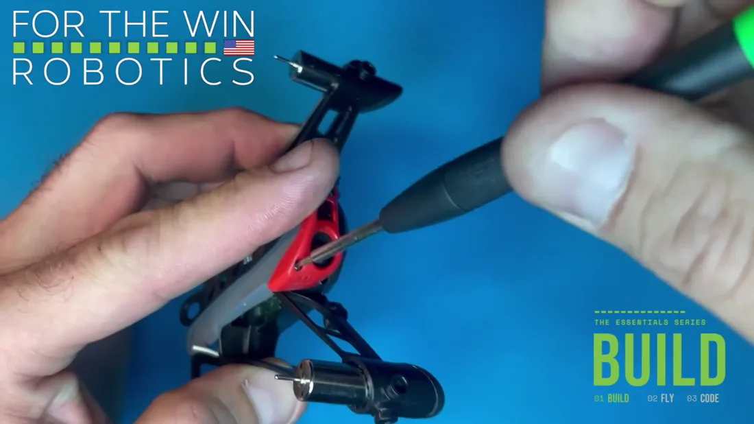
Drive the screw until it reaches its first stop. That is all it needs.
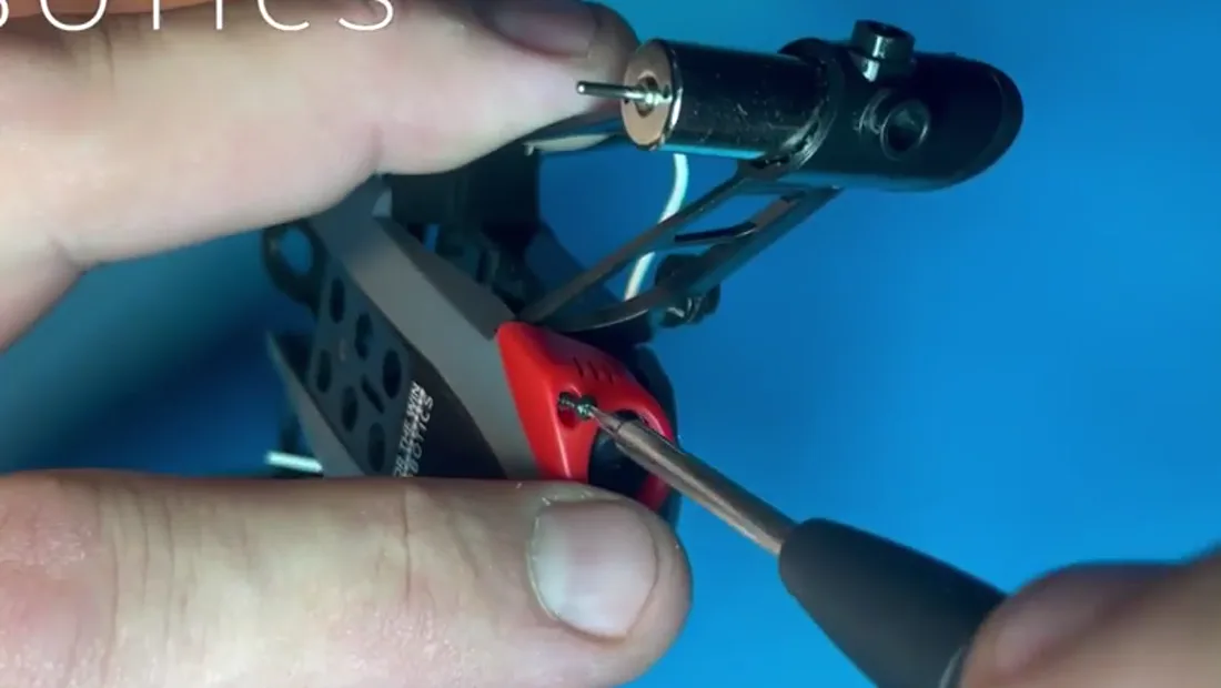
Second screw the same. Do not press down. It should find thread without force, and pressing is how small screws go flying.
Top body panel, front screw
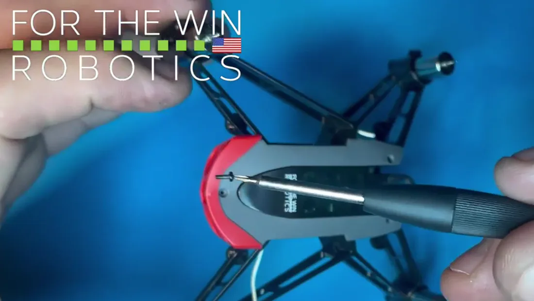
One screw goes in beside the face mask, holding down the front of the top body panel.
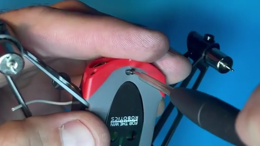
Drive it through the panel's plastic first, then go looking for the airframe hole underneath.
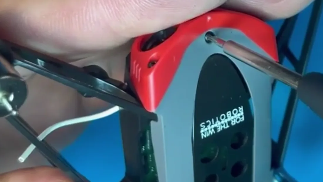
The top body panel's holes are tighter than the rest of the holes on Hopper, which is exactly why you clear the plastic before you start hunting for thread.
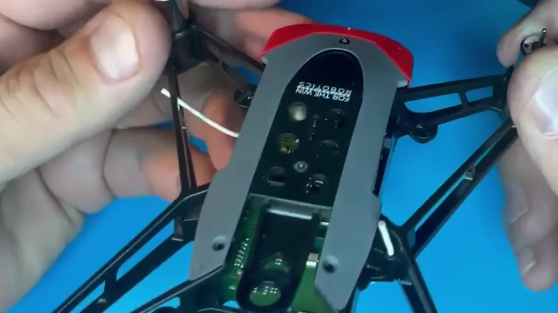
Leave the two rear top panel screws open for now.
Bottom body panel
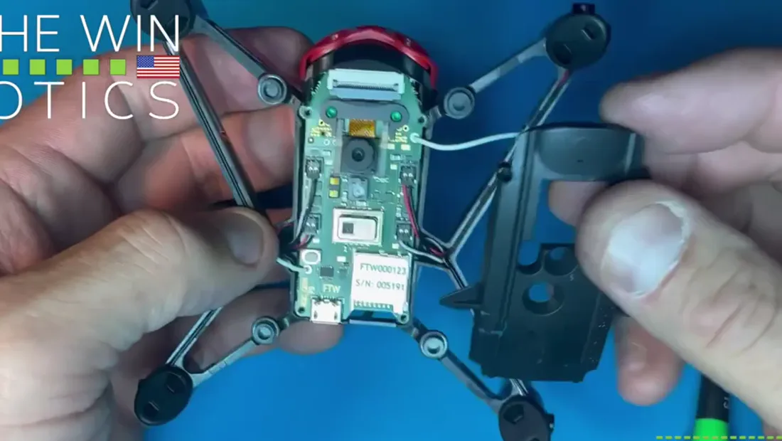
Flip Hopper over. This is a critical piece, and it only goes on well if everything underneath it is already right.
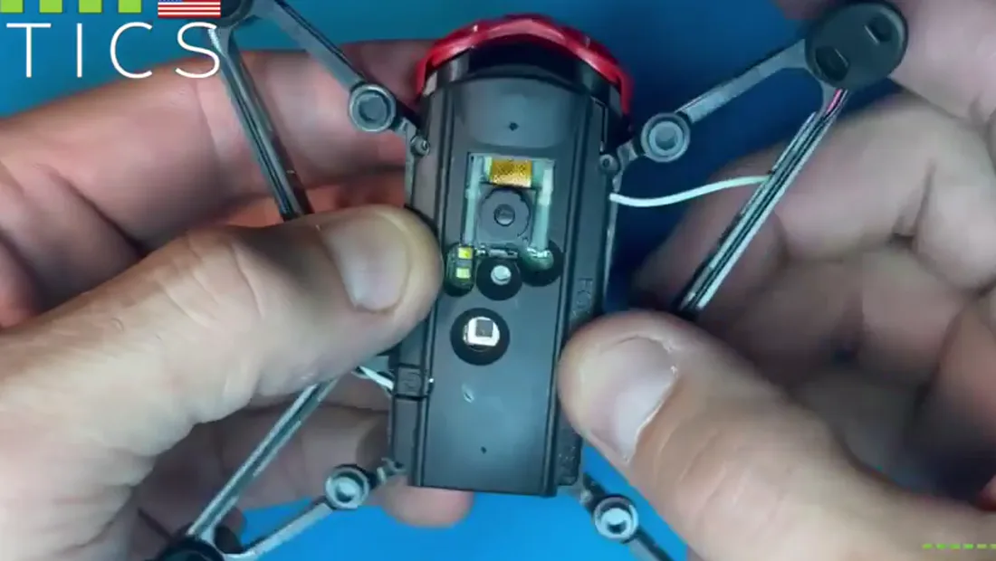
Check three things first: motor wires tucked properly into their channels, both antennas in the channels cut for them, and the tray the lens sits on clear of the panel.
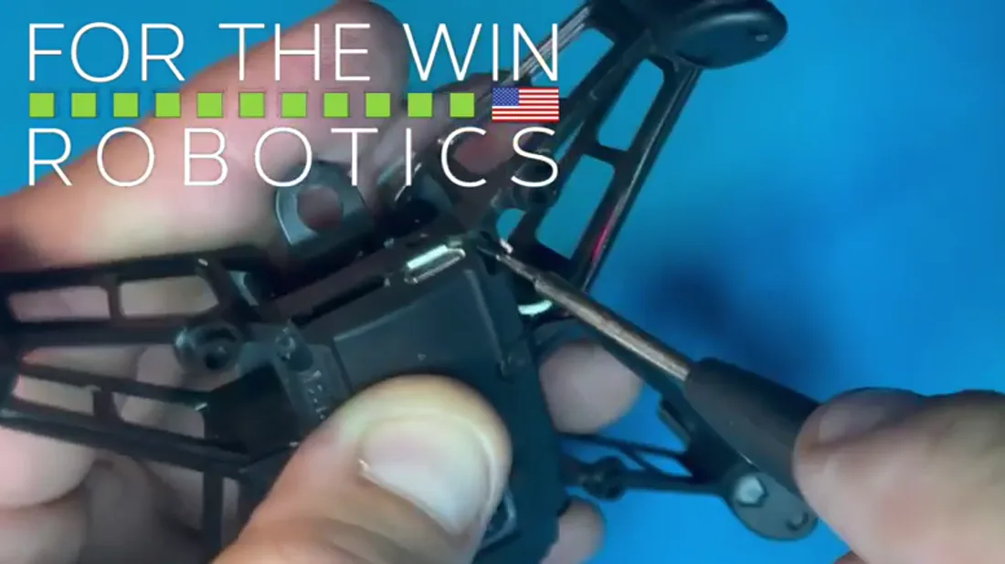
Line up the four holes and start with the rear two. One side at a time is the easier path.
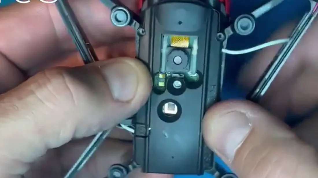
If a screw turns without drawing the panel down, stop. Check the alignment between the panel and the board rather than forcing it.
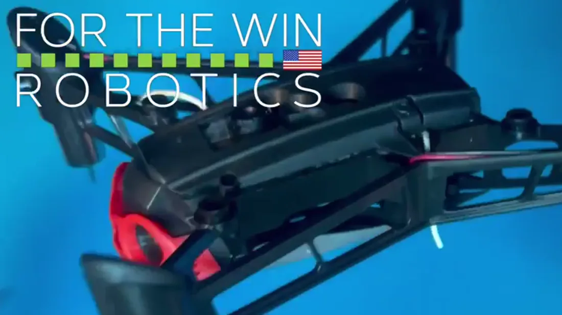
Close the gap until the screw stops. Tight enough to close it, not tighter.
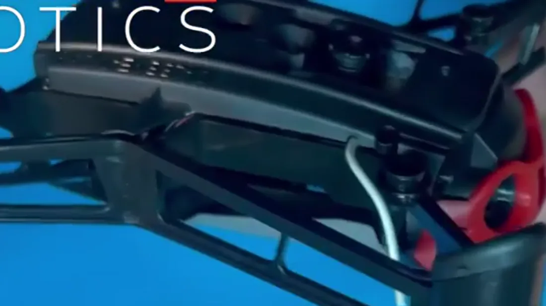
Done right it sits flush and flat, the antenna comes out through the hole meant for it, and there is essentially no seam.
Module port cover, the top hat
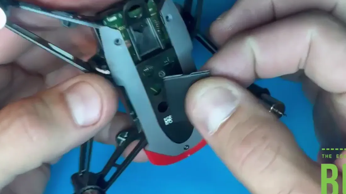
The top hat covers the module ports, the Lego style holes on the top of the airframe.
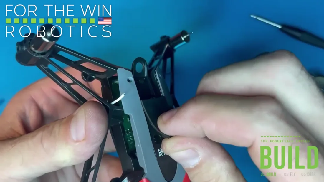
Put all six holes onto the airframe holes and press it down flat.
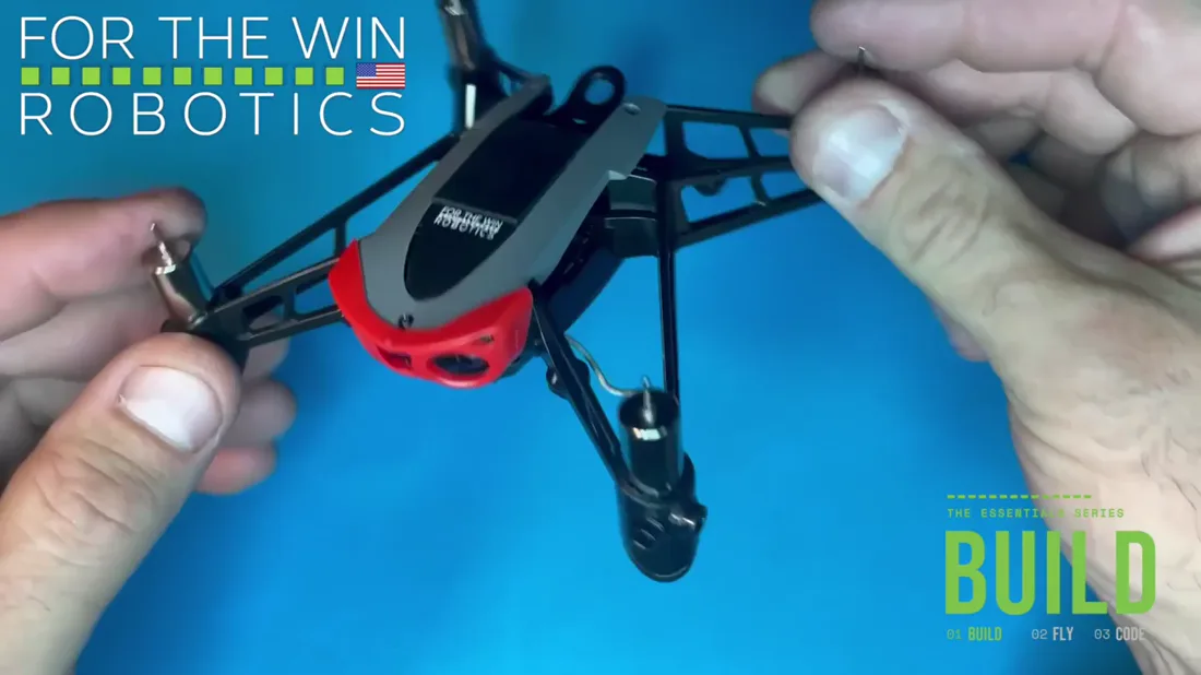
Covered, they keep the PCB protected for as long as nothing is attached to them.
Top body panel, rear screws
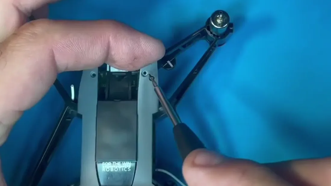
Two screws left, the rear pair on the top body panel.
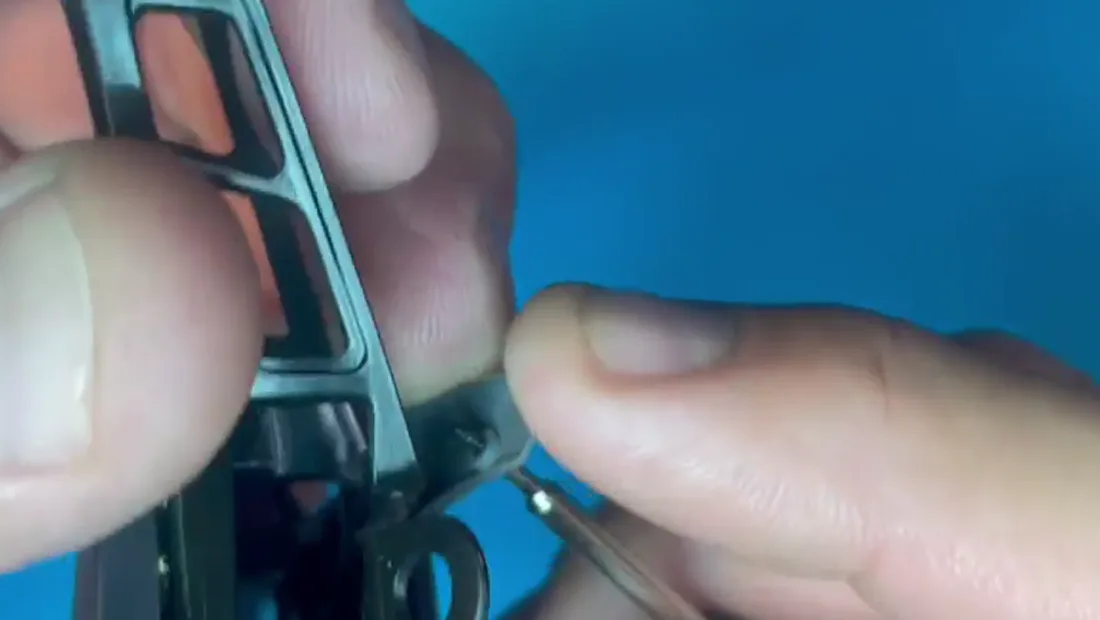
Same technique as the front one: through the plastic first, then into the airframe hole.
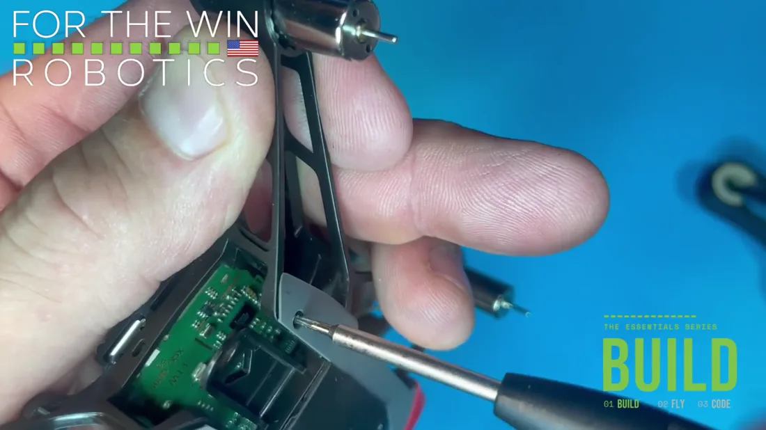
Down until it stops. It does not need to be tight. Same on the other side.
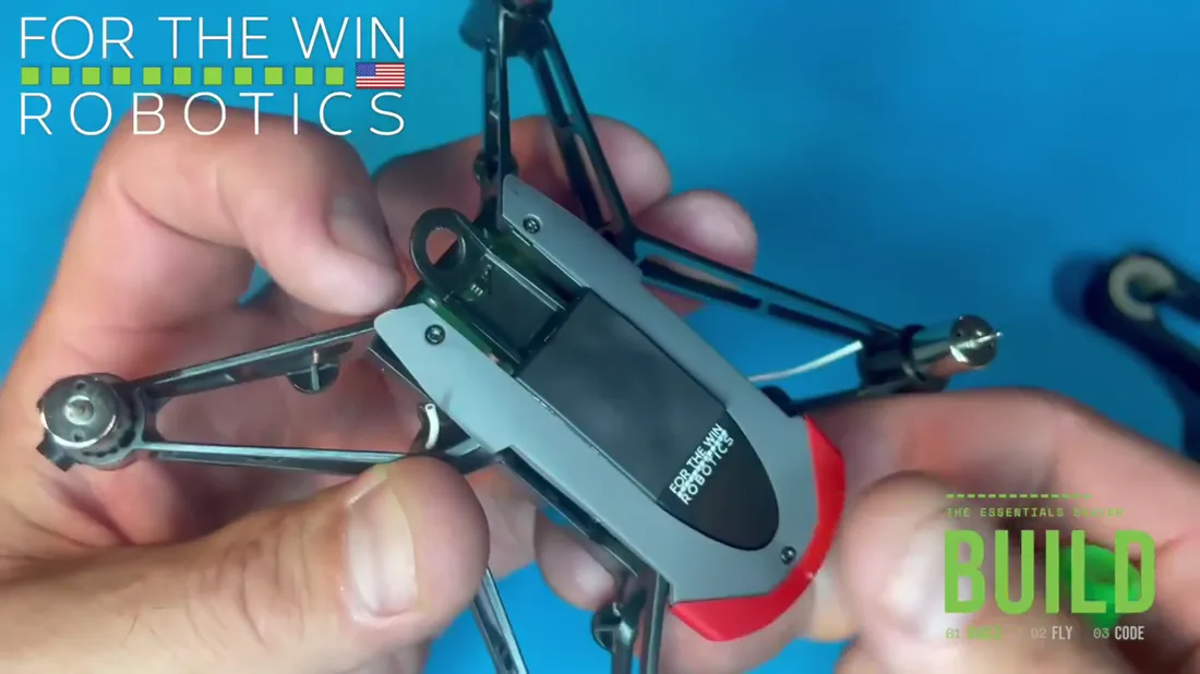
The top of Hopper is now fully closed and protected.
Propeller install
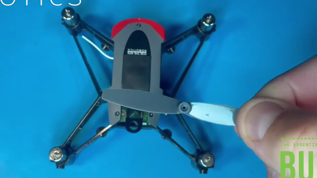
Propeller A is grey on current sets, and every A carries an A on the underside of a blade.
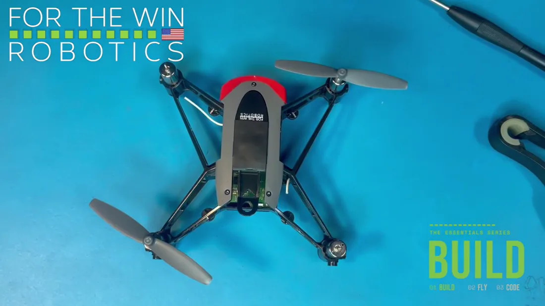
Propellers follow their motors, so the positions are already decided. Propeller A goes front right and back left. Propeller C goes front left and back right. Each pair sits diagonally across the airframe, exactly like the motors do.
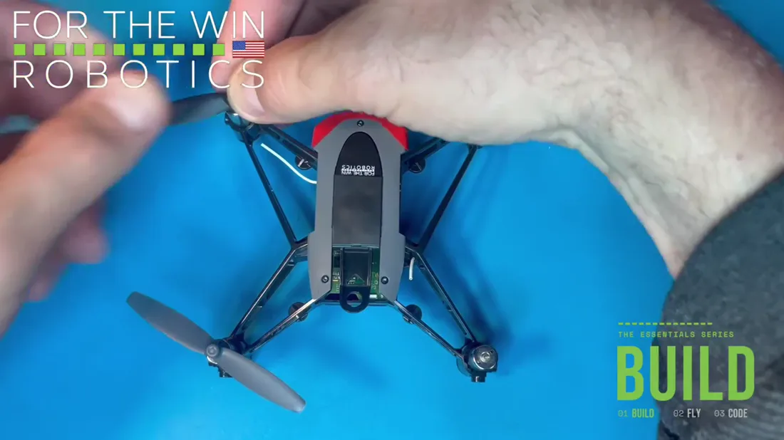
Press all four down firmly onto their motor shafts, all the way in, so each propeller sits on the motor, or just about.
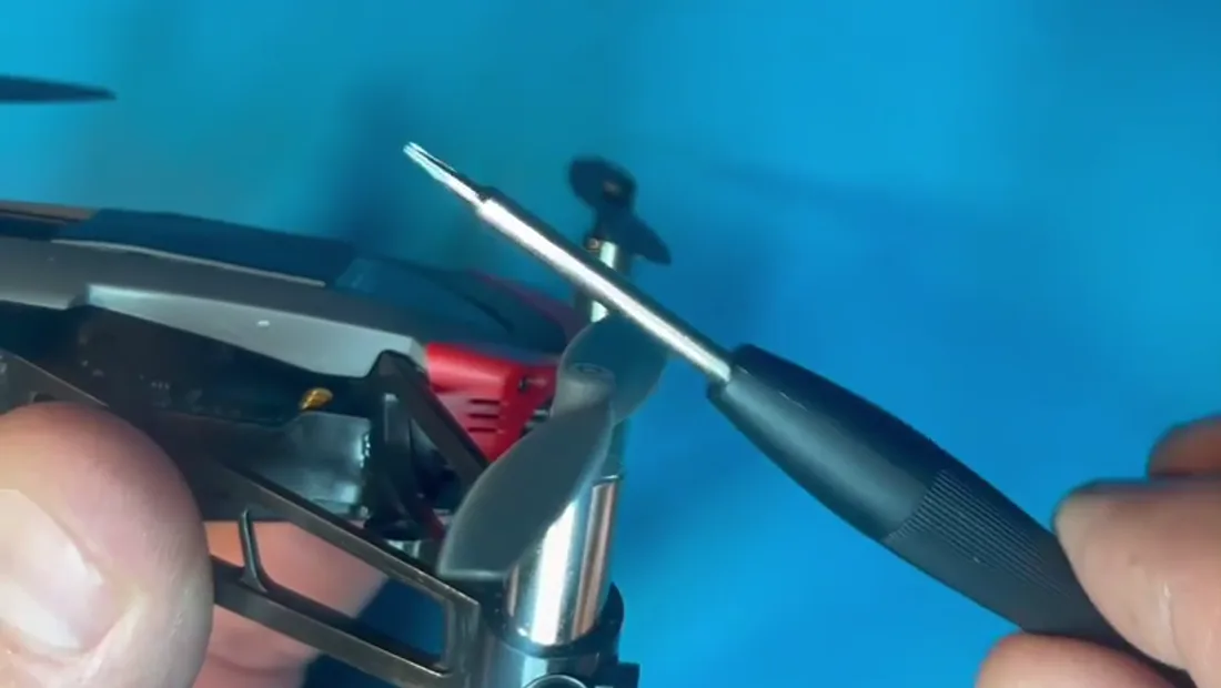
Now run the orientation test, which is what proves the orientation is correct. Look at the two front propellers, at the inner blades that point toward each other. They pitch from down to up as they come toward you.
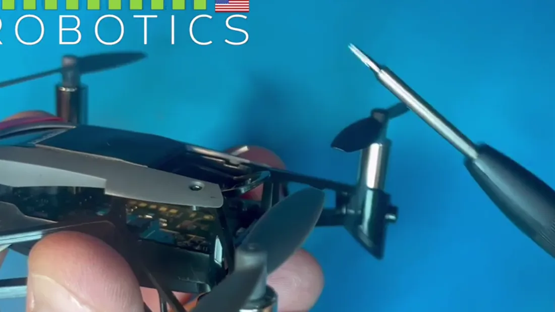
Then do the same test at the rear. Those inner blades also rise from down to up, the opposite of the front, so the two pairs together follow one line up and over Hopper.
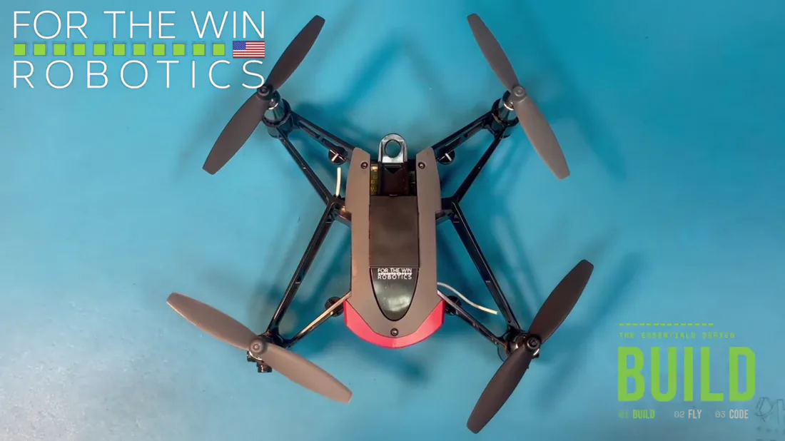
If a pair does not read that way, take that propeller off and swap it to the other diagonal.
Colour is a convenience for telling your drone from someone else's. The blades are what identify the part.
Propeller guards
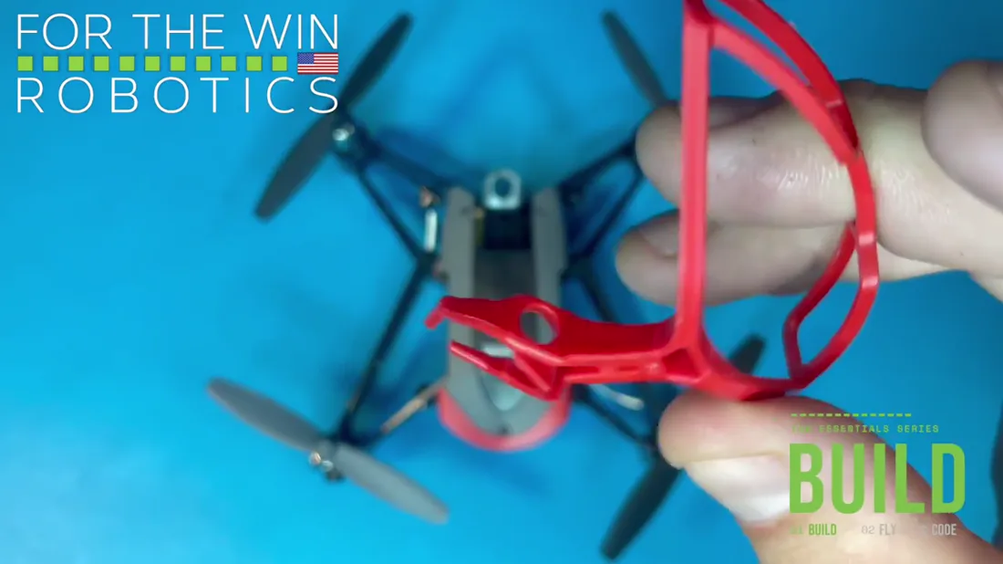
All four guards are the same, and any one fits any motor mount.
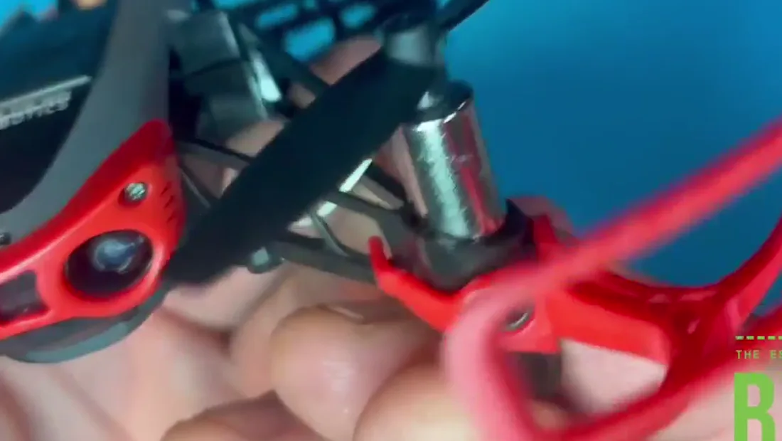
The arms go around the motor mount, inside the airframe.
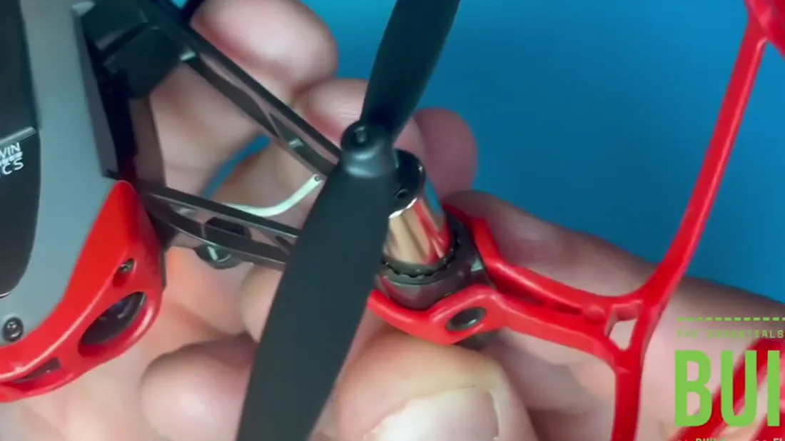
Each of the two airframe protrusions on the outside of the mount takes one of the guard's two holes.
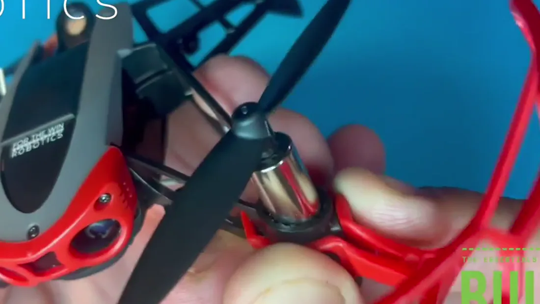
Squeeze until both sides lock in. It takes a little finesse.
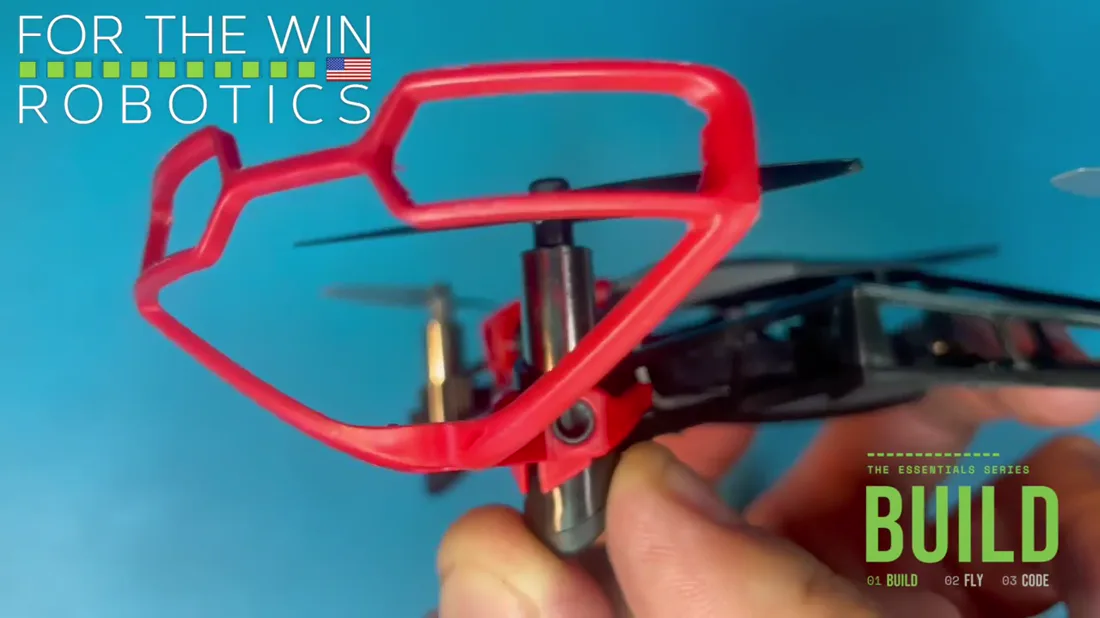
The guard curves up and over the propeller it protects. If it is facing downward, it is on upside down.
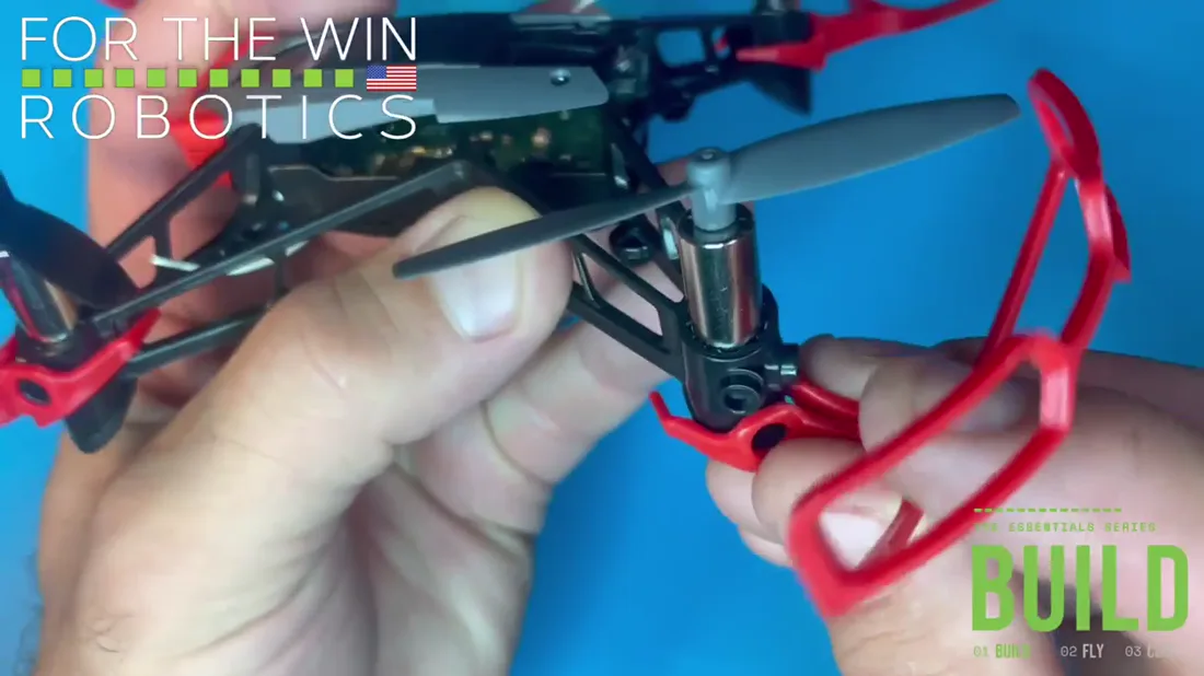
Repeat for the remaining three the exact same way.
Battery and calibration
All three of Hopper's batteries should already be charged. You started them charging before the build so they would be ready when you got to this point.
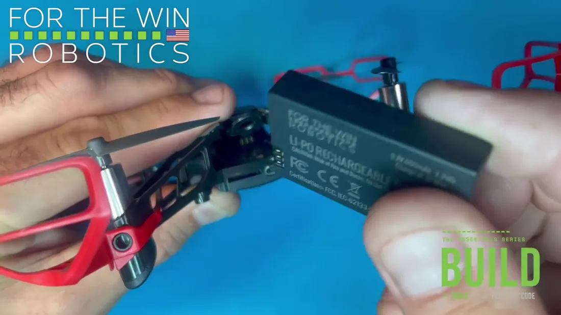
The battery's contacts point down, to meet the three bars at the back of the PCB. Flip the battery over so the sides match.
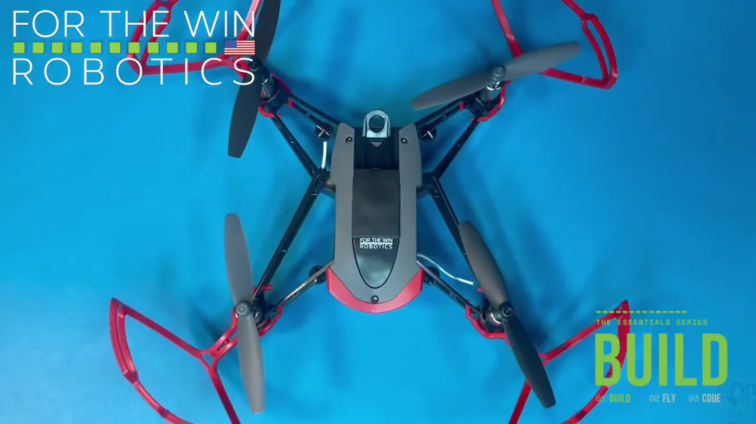
Set Hopper down on the floor before you insert the battery. Calibration begins the moment the battery clicks in.
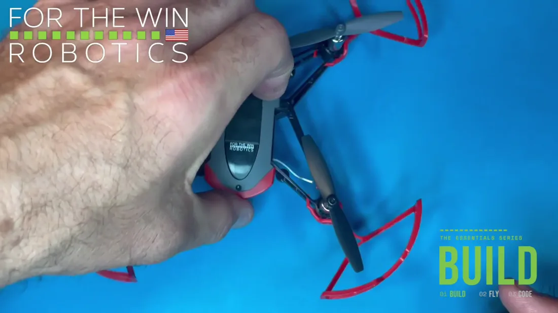
Locate the battery port at the rear of the drone. Line the battery up without bending the propellers, and click it in.
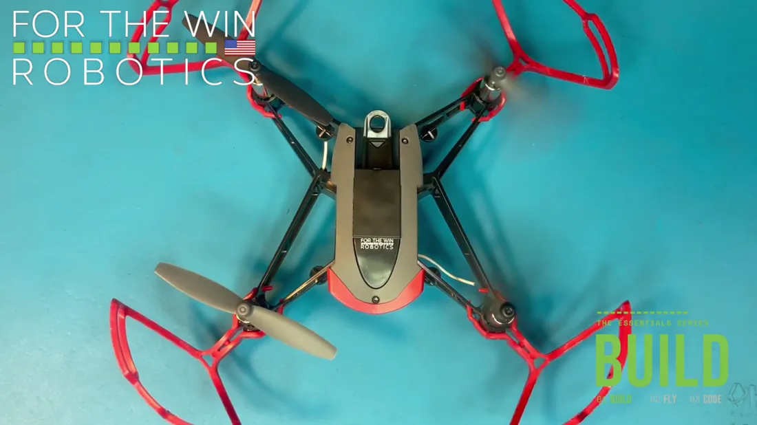
Watch the propellers, not the lights. Calibration lives in the props, and they run an opening sequence the moment the battery clicks in. If they do not execute that sequence correctly, something is wrong. On firmware 2.0.6 this is what a normal power up looks like.
The propeller tool is the easy way to get a battery back out once it is seated.